Flippy Cube
The Flippy Cube concept was designed for the exploration of how physical manipulation and orientation could be used to control the colour and intensity of a light-emitting surface on the cube. Flippy Cube's interactions are powered by an Arduino Pro Micro which uses tilt sensors and a gyroscope to detect orientation and rotation.
Video
Arduino Code
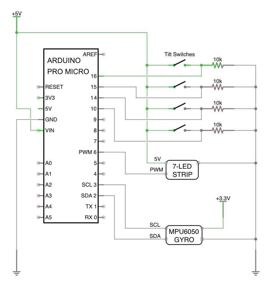
https://github.com/MarkErik/flippy-cubeFlippy Cube Circuit Schematic
The Story
Flippy Cube almost didn't happen.
The initial idea was something I'll call Fally Tower. A simple tall lamp that would be lit when upright, and turn off when it fell over.
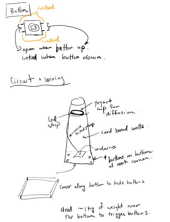
Fortunately, Prof. Oehlberg challenged me to consider how the physical characteristics of the artifact could communicate or encourage interaction. The idea was then to have a series of blocks stacked on top of each other, as the motivation was a design that would encourage knocking something over, so that when it fell, the light would turn off.
The birth of Flippy Cube
To start prototyping the concept, I took a box, put some green tape over one end to signify the light, and immediately I began wondering, what would happen if I rotated it? What would happen if the light wasn't facing up, or down, but instead on its side?
That brought me to my first mini technical challenge - a tilt sensor can very easily signal if something is upright, or facing down. But if the box is placed on its side (with the tilt sensor mounted straight up and down), the ball inside the tilt sensor would just be rolling around, and give erroneous values.
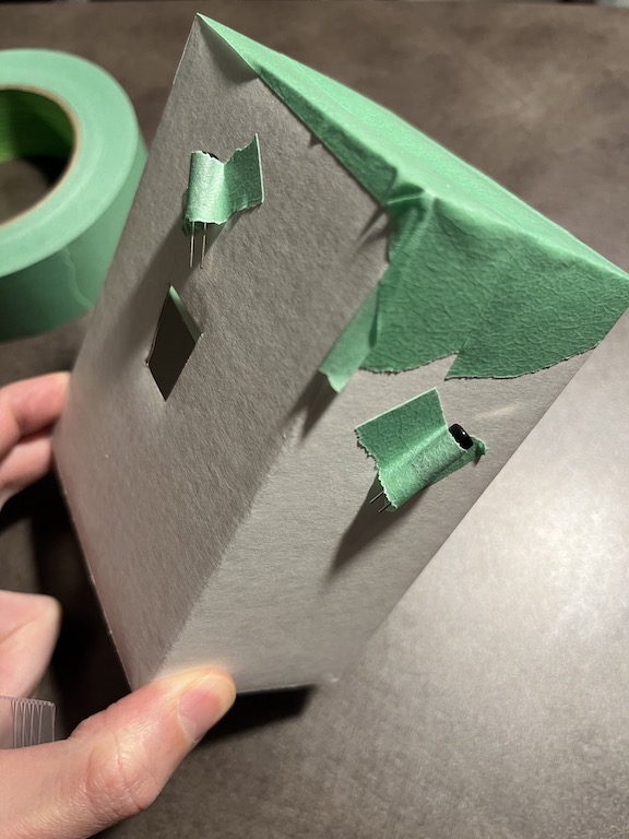
To overcome this, I decided to place the tilt sensor at a 45-degree angle, so that only when the box was turned fully upside down, would the ball roll away from the contact pins. But this presented another problem - I also wanted to explore what would happen if I rolled the box while it was on its side. However, the angled tilt sensor would only work in one orientation, and so if I were to roll the box while it was on its side, because of the angle of the tilt sensor, there would be positions when the ball would roll away and break contact. To address this, I attached another tilt sensor, on the opposite side of the box, angled 45-degrees, but in the opposite direction, so that when the box is rolled onto that side, the tilt sensor would still be facing up. This would allow me to use logic in the code to look for when the tilt sensors on opposite sides have one sensor which is LOW and the other HIGH.
Adding the rotation and frying my first sensor
TLDR; My fault for not paying closer attention to the positive and negative rails on the breadboard - assuming that the positive rail is on the outside on both sides of the breadboard.
To detect rotation, I used a commonly available, low-cost sensor, the MPU6050, which provides gyroscope, acceleration, and temperature sensing. It also needs 3.3V instead of 5V which I had been using for all the other components. The breadboard power supply that I used has the ability to select the voltage that it feeds the rails. I had been using the 5V rail the entire time, where the positive side is on the outside. I turned on the 3.3V supply, but didn't notice that the positive side is on the inside rail. I hooked everything up from muscle memory, red wires on the outside rail, black wires for ground on the inside rail. I powered up the Arduino, ran the sample MPU6050 code...and nothing happened.
This must be a problem with code I was thinking. So I was re-checking the code, the libraries, etc. All the while, the poor little MPU6050 was being powered wrong - and getting quite warm (after I realised the wiring problem) - but "fortunately" no magic smoke. After I confirmed the code looked good, I then checked the wiring, and found my mistake, fixed the power wiring, and turned everything back on, and the power LED to the MPU6050 board turned on. Now, I wrote fortunately in quotes, because had I known that I really cooked the MPU6050 then, I could have saved myself 5 hours of trying to figure out why it wasn't working. After trying multiple libraries - turns out lots of people have made Arduino libraries to interface with MPU6050 sensors - I used the I2C scanner (linked in the Resources section below) - and found out that the MPU6050 was showing up on the bus at address 0x77. So I figured all was good still with the sensor, the power was on, and it was detected on the I2C bus. How wrong I was.
After much more testing and searching, it turns out that the MPU6050 *really really* should ever only use the address of 0x68 or 0x69 - and that is what all the libraries are looking to talk to it at. Anything else means either the chip is damaged (likely what I did), or faulty, as there are lots of knock-off chips floating around.
So how did I move forward? I had another gyro sensor, based on the MPU6500 (which has much less support and libraries available), which I wired up (correctly), started the Arduino, and yes! got communication and gyro readings. Unfortunately, the readings were not very easy to parse into detecting rotational movement. At that point I figured rotation detection would be a stretch goal.
At the Electrical Maker Space and a new MPU6050
The following day, I had planned to start building the final prototype, using the wires and tools at the Electrical Maker Space on campus. As I was gathering my materials, I found out that they also had a bag full of MPU6050 boards!
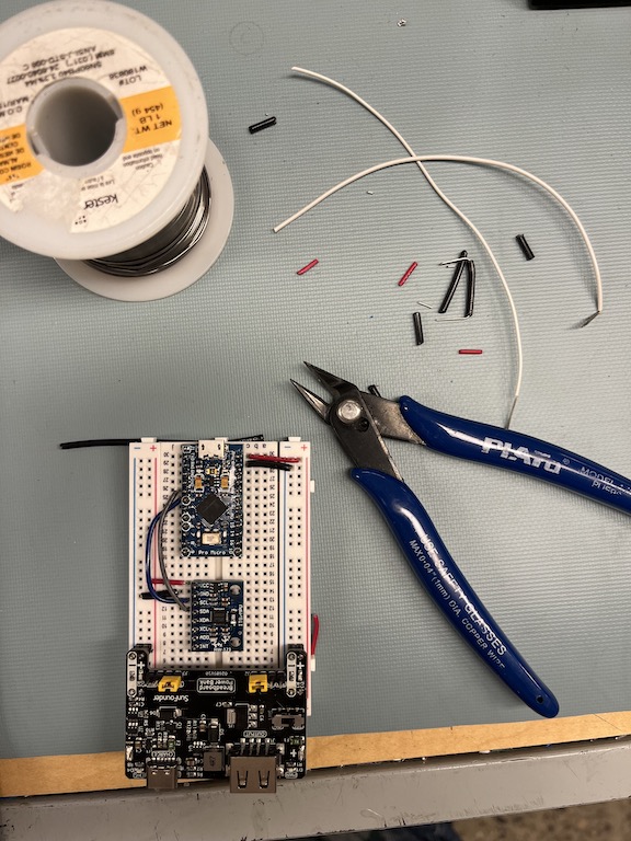
I quickly wired one up, ran the MPU6050_light library, and not only did it work, the gyro readings were exactly what I would want to interpret rotation!
Putting it all together
To increase and even-out the light output from the LED-strip that I was using, I created a short compartment at the top of the cube that I lined with aluminum foil (shiny side up).
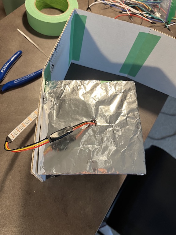
I then attached the tilt sensors to the inside of the cube, and wired everything up, using tape to secure the leads to ensure that as the cube was rolled and flipped, nothing would come loose.
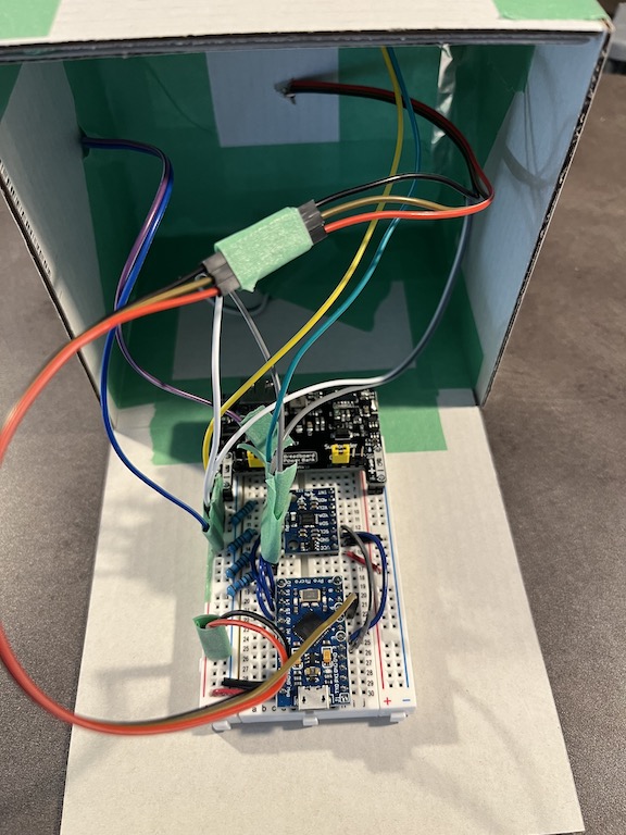
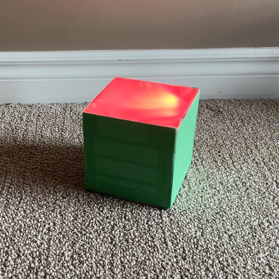
Throughout the assembly process of Flippy Cube, I was testing the code, trying the rotation, and the color-changing on-its-side rolls. It was a bit akward since I would be holding the bottom piece in one hand and cradling the rest of the cube in my other hand. Everything seemed to work well. So I "sealed" it up and Flippy Cube was ready for the world.
What I missed, and what I'd like to fix
When I said that it seemed like everything worked well, that was my assessment after interacting with the almost complete cube. However, once I could manipulate the cube in its "finished" / "robust" state, there was one aspect of the interaction pattern that I found wasn't consistent with expected light behaviour. Interestingly, this problematic behaviour only became apparent (at least to me - meaning that maybe someone else could have spotted it sooner) when I was trying to use it in a real setting.
The issue occurs in the scenario when the cube is on its side and you roll it to pick a colour, for example, red, and then orient the cube upwards to adjust the brightness through the rotation action. Once you have "dialed in" the brightness you want, my expectation is that if I were to place the cube on its side, it would retain the color, in this case, red. However, the color will likely change, because after the rotation to adjust the brightness, it will now be in a different orientation when placed on its side, and it will change the colour based a set of hard-coded values corresponding to the combination of tilt sensors in their HIGH and LOW states - rather than maintaining the color which you started with.
To address this inconsistency, I'll leave this to future work, as my Monday 7am exploration before classes highlighted that it would require a fair bit of reworking to the logic of how I interpret the tilt sensors, as well the debounce logic.
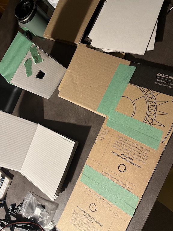
Post script: Everything out of cardboard
References and Resources
Throughout the course of developing Flippy Cube, these were some of the key resources I used:
Arduino I2C Interface
Connecting the MPU6050 gyro sensor uses the I2C (Inter-Integrated Circuit) bus (Serial Data - SDA, and Serial Clock - SCL) on the Arduino. There is a great resource about how the bus works on Arduinos as well as I2C scanner code at: https://gammon.com.au/i2c
MPU6050 Gyroscope and Accelerometer
The MPU6050 sesnor that came from my SunFounder Arduino kit suggested that I use the Adafruit sensor libraries: Adafruit - MPU6050 6-DoF Accelerometer and Gyro, which also had sample code and connection diagrams at the SunFounder website: MPU6050 (Basic Project). Ultimately, after much trouble-shooting, I found the MPU6050_light library easier and more reliable to work with: https://github.com/rfetick/MPU6050_light.
Pull-o-Phone
The Pull-O-Phone was motivated by the idea that creating music and sound takes effort, and this was represented through the act of having to use force to pull and shape the sound.
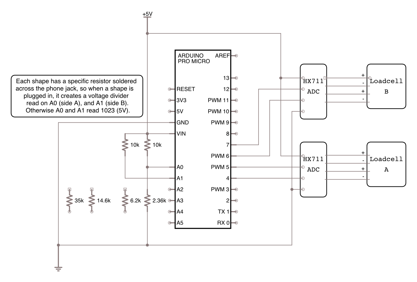
Pull-o-Phone was implemented using an Arduino Pro Micro wired to load sensors via the HX711 ADC as well as using analog inputs, sending data to SuperCollider which controlled four Synths, activated depending on which physical object was plugged in.
The objects were chosen to explore how the feelings of shape (for example hard edges of a square), or the roundness of a cylinder affect the sound that is produced. Size and weight also contribute to the interaction. Finally, texture was also investigated as another means to alter the sound.
Video
Arduino, SuperCollider Code, and 3D Models
https://github.com/MarkErik/pull-o-phonePull-o-Phone Circuit Schematic
The making of Pull-o-Phone
Inspiration: The sound of the the Interstellar movie score.
When the assignment was presented, it made me think about the long drawn out sounds used in the Interstellar soundtrack composed by Hans Zimmer (turns out it was an organ!). It evoked this idea of having to pull something to generate sound, and that the amount of effort would influence the resulting sound.
Load Cells - simple yet not.
In lieu of having stretch sensors, I wondered whether a Load Cell (essentially a sensor that can measure weight) typically used for scales, could be adapted with an elastic band, and provide workable values.
The load cell worked to provide what I would interpret as stretch values, so the next step was connecting it to SuperCollider.
I found a great tutorial by Eli Fieldsteel (linked in references section), for sending data from the Arduino to SuperCollider. However, I immediately noticed that there was a significant delay when applying or removing force. Not at all a satisfying experience for controlling sound. Investigating this, I looked at the source code for the library that was developed for the HX711 ADC and it does smoothing over 16 values, with the goal of improving accuracy of the scale reading. I was able to set the parameter for smoothing to 1 sample, so that it would just send the values as they were received.
Thinking that I now had a responsive sensor, I fired up SuperCollider - and noticed that while there wasn't a delay anymore, the sensor seemed choppy for lack of a better word. After much investigation, it turns out that by default the HX711 samples at 10Hz, but it does have an 80Hz mode. Unfortunately you need to cut (in my case butcher/scrape) a circuit board trace and bridge two microchip leads...
Once it was running at 80hz, it was very satisfying!
The physical aspect of Pull-o-Phone
I'm not sure why, but I decided that for this assignment I would 3D-print all the parts.
This was truthfully a baffling decision. I had never 3D-printed anything, nor actually used CAD software to design something to be 3D-printed.
I didn't abandon cardboard entirely, my first early prototype was just boxes, tape, and elastic, which was sufficient to make me say, this can work, lets just make this real by 3D-printing it. And it seemed like an "easy" way to get all the shapes that I wanted to explore.
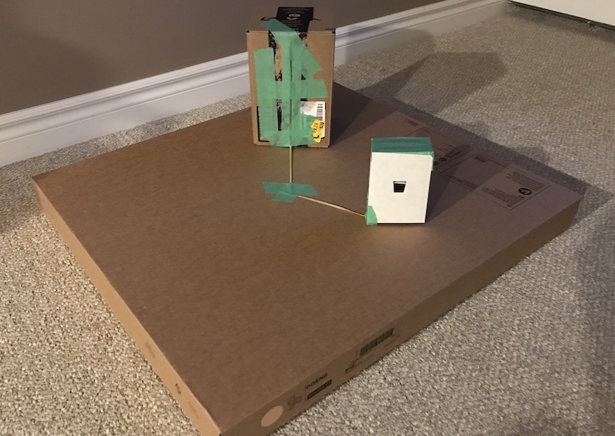
I'll skip the details and just say TLDR; It added so much stress trying to do it this way, but in the end I am very happy to have had this opportunity that forced me to learn how to 3D-Print, and it allowed for really good connections for the components to work together.
The mapping challenge
My goal was to have a number of shapes, where I would try to capture some of the physical characteristics and map them to sounds that you might expect - which I think is an interecting challenge, since what does a square sound like? Is it just a square wave (instead of a sine wave?) (Not really, both just sound like tones) What does a bigger square sound like? Does how heavy the object is affect your perception of what it should sound like. The printed objects come out smooth, what if they had different textures?
Initially I had also wanted to explore colour, but I also wanted the instrument to be accessible for people with different levels of vision - so while colour may be interesting, I opted not to make that a design parameter.
Mapping shape, size, weight, texture into sounds via SuperCollider was a challenge - largely due to the non-trivial aspect of programatically creating sounds. I was happy with what I could map for the demo and within the time alloted for the assignment. This is certainly an area of future work where once expertise is gained in SuperCollider, there could be an even more natural link between the physical characteristics and the associated sound created.
References and Resources
The two key areas where I needed resources were for improving the performance of the HX711 ADC and working with SuperCollider:
Modifying the HX711 to run at 80 samples-per-second
By default, the HX711 is set to run at 10 samples-per-second which is too slow to have a responsive feel for the instrument (supposedly for accuracy, but I did not find a difference once running faster). In Google'ing for why the sensor was so slow I came across the following discussion on the Arduino Forums that described what needed to be modified on the HX711 circuit board to enable 80Hz mode: https://forum.arduino.cc/t/hx711-soldering-for-80-hz/630699
Fantastic SuperCollider YouTube Resource
Eli Fieldsteel, an Associate Professor of Music Composition-Theory and Director of the Experimental Music Studios at The University of Illinois Urbana-Champaign has been publishing SuperCollider tutorials, live coding, and lectures for a number of years on his YouTube channel: https://www.youtube.com/@elifieldsteel
Sweet Insight
Sweet Insight is an exploration of how a person’s blood glucose levels could be visualized physically.
As someone with a family history of diabetes and poor blood glucose control, the motivation for Sweet Insight was to create an awareness of blood glucose levels, through a glanceable, ambient physical display.
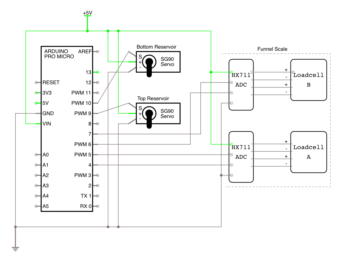
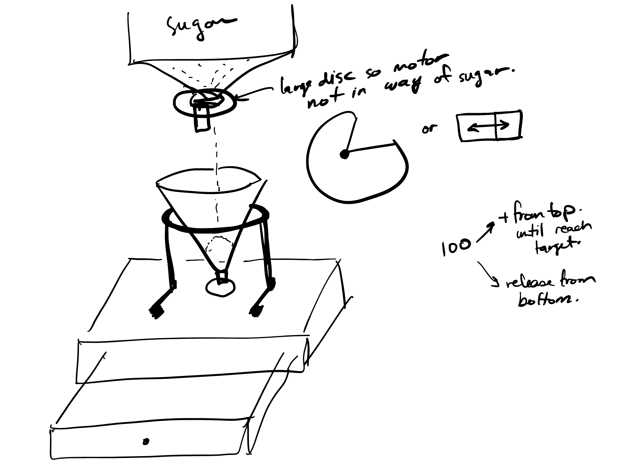
A glass funnel filled with adjustable levels of sugar represents a person’s changing blood glucose levels. The weight of the sugar in the glass funnel is measured by 2 load cells in the base of Sweet Insight and the mapping used is 1 gram of sugar to each mg/dL of blood glucose. As blood glucose rises, for example after a meal, sugar is released from the top reservoir, controlled by a servo. As the body produces insulin, or uses energy, the blood glucose level decreases, and sugar is released from the funnel into a lower reservoir, controlled by a servo.
Sweet Insight Video
Arduino Code and 3D Models
https://github.com/MarkErik/sweet-insightSweet Insight Circuit Schematic
Creating a sweet insight
Inspiration: Just like sand piling up in an hourglass, my blood glucose sometimes just wants to keep rising.
As soon as I heard the assignment prompt to visualise personal data, my first thought was to use the data I get from my wearable continous glucose monitor (CGM). In one sense, I'd say I am lucky to have access to a very personal dataset, however, in another sense, it is not so great to be always thinking about what my blood sugar levels are.
With the data, I was imagining something pouring, and I also liked the idea of how sand piles up in an hourglass. I went with a pretty direct metaphor of using granulated sugar to represent blood glucose levels.
Do you want some sugar in your coffee?
Finding a transparent funnel to act as the container to show the sugar as it piles up, wasn't so straightforward. After scouring Amazon and thrift stores, I found plastic translucent, but not transparent funnels, and the glass ones I could find, were reviewed as being sharp, dangerous, and often arriving broken.
I was convinced that a clear funnel shouldn't be so hard to find.
Coffee to the rescue. Well, actually, pour-over-coffee funnels to the rescue.

I was happy to find a funnel, but it came with its own problem - the opening at the bottom was very large. It would be difficult to control the flow of sugar.
Controlling the rate of flow
To control the rate of flow when releasing sugar from the funnel, and due to the protrusion at the bottom of the funnel, and because I needed to weigh how much sugar was in the funnel, I had to create a multi-piece mounting system - with a servo controlled flap.
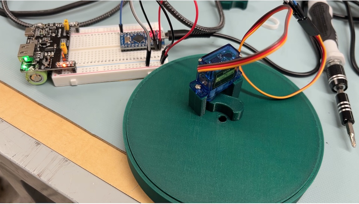
With the servo mounted with the flap, I was able to control the release of a stream of sugar - however, integrating all the pieces took quite a while
Because the top reservoir had to be supported by the base, yet the funnel had to be independent of the base, so that I could measure its dynamic amount of sugar - the funnel needed to be on a floating base in the center. Because I was 3D Printing the components and I was trying to follow good printing principles e.g. limit overhangs, and print from bottom-up -- it meant that lots of little mounting pieces had to be created, and measurements had to be precise, so that everything would fit together at the end.
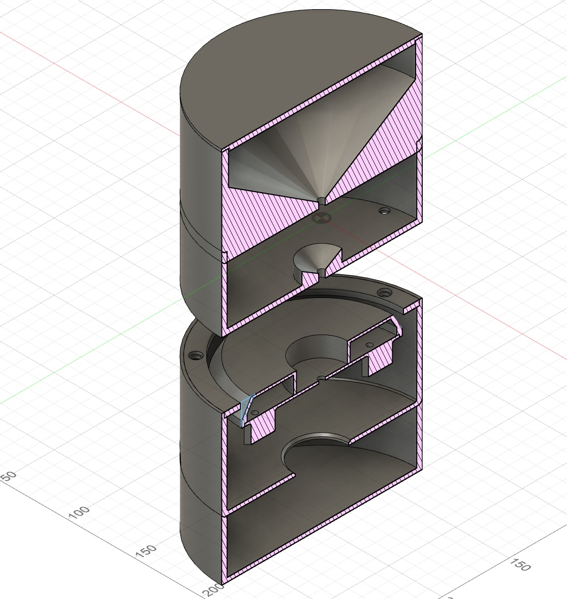
I was pleased with how it all turned out - a minor change is that I'd raise the top reservoir even higher, so that the sugar level in the funnel is easier to see from a higher angle, rather than having to look straight on.
Future directions - forget blood sugar just visualise sugar with sugar!
As I was using Sweet Insight, the concept of having something physical that I could glance at which represented blood glucose, was nice and fun - however, I could also just look at my smartwatch which has a widget for the the Dexcom G7 CGM that I use. For me, the number is what I really want to know - for example a morning fasting blood glucose of 105 mg/dL is indicative of pre-diabetes, whereas just a few points lower, say, 95 mg/dL is considered within a normal range.
Looking at Sweet Insight and thinking about the sugar piling up and what it could also represent, I realized that a concept which relies perhaps less on an exact number, but more of a quantity or volume, is the amount of added sugar one consumers in a day.
I think it could be quite compelling to link up with a food tracking app, and dispense the amount of added sugar for each item that you log - so that at the end of the day you have a very direct representation of the amount of sugar you consumed. I feel like this could help both those with blood glucose management problems as well as those perhaps unaware of the amount of added sugar in our food supply.
References and Resources
To create the demo mode for the class presentation, I needed a way to send blood glucose values via the serial monitor. There is a defualt serial.read function, however it is blocking, and doesn't behave well if entering a few digits at a time.
Reliable, robust, non-blocking code to read text entered from serial monitor
I was fortunate to find a post on the Arduino support forums where a user shared a number of different methods for reading values from the serial monitor: https://forum.arduino.cc/t/serial-input-basics-updated/382007/3
Fight to Relax aka sooo many wires
Fight to Relax is a set of prototype tangible input devices designed for the game A Blind Legend. The premise of A Blind Legend is that you play as a blind medieval knight trying to save his wife who was captured by an evil king. This game was developed in 2015 by Dowino, where the objective was to design a game that requires no visuals, and relies only on audio, and thus could be played by people with varying levels of vision.
The Fight to Relax project was motivated by wanting to design an experience that could be used post-panic attack by people who have a heightened awareness of their own physical sensations, for example, the beating of their heart, tremors and shaking of their body, or experiencing difficulty focussing with their eyes. Being able to close your eyes and play a game which would engage your attention on something other than your physical symptoms could be helpful in the process of calming down after a panic attack or stressful event.
However, and unfortunately, the game chosen is not very relaxing to play, but the physical controls created could be adapted for use in other experiences.
Fight to Relax Video
Arduino Code
https://github.com/MarkErik/fight-to-relaxFight to Relax Circuit Schematic
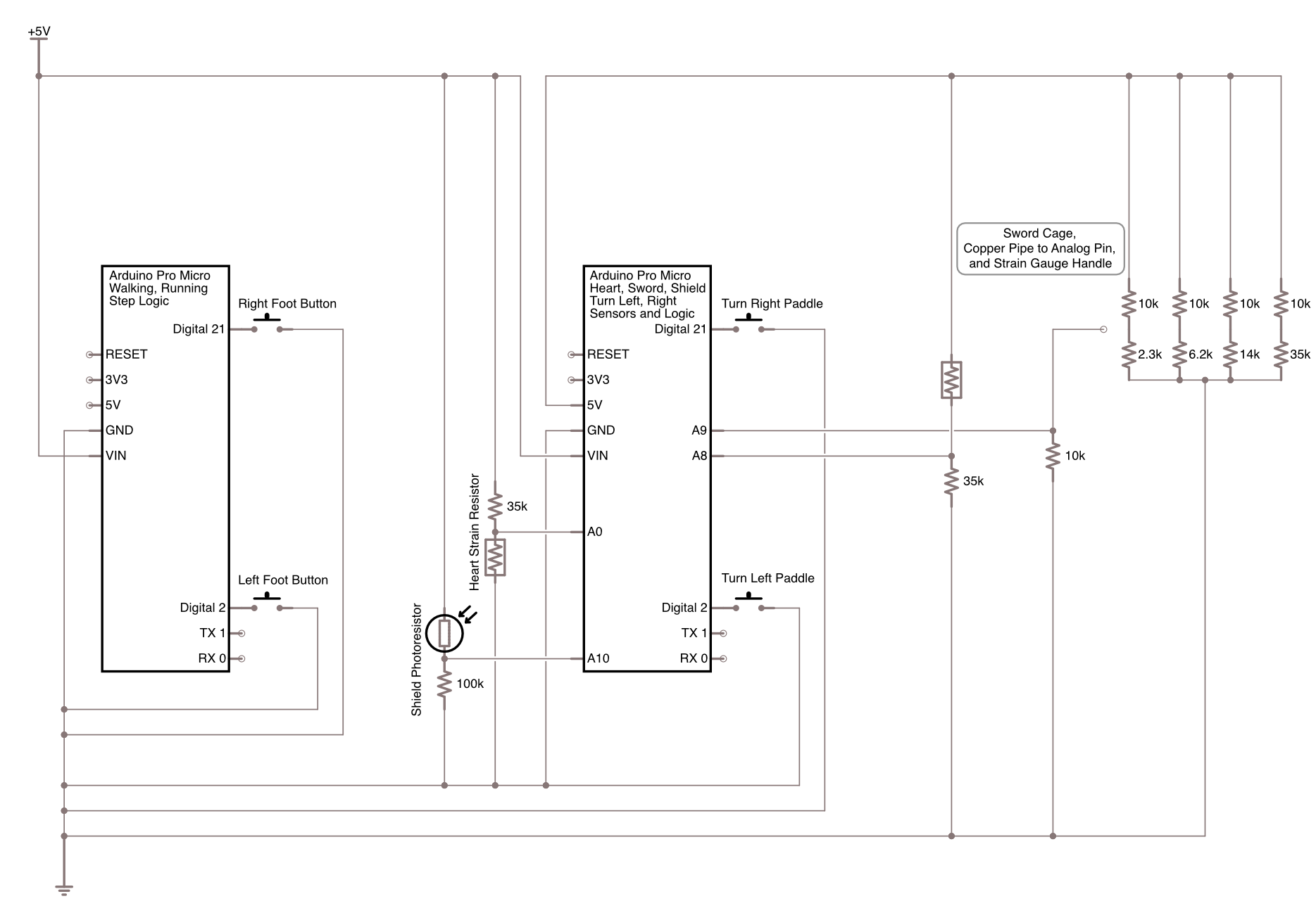
The Saga of Fight to Relax
Why is it that trying to relax can be such a struggle?
Many people are able to close their eyes, take deep breaths, do a mindful body-scan and start to feel more relaxed.
But for some people (i.e. me), if I am feeling anxious, and if I close my eyes, all I notice is how quickly my heart is beating, or other uncomfortable phsical symptoms of anxiety. My mind begins fixating on these sensations, and it can start an unpleasant spiral. My typical coping stategy is just to scroll on my phone, to distract myself until I start to feel better - but its not ideal.
Often, when experiencing anxiety, I find that it is difficult to focus with my eyes, and so I've been thinking about if there was something I could do with my eyes closed, that wasn't the typical mindfulness exercises, where I could relax and direct my attention away from my physical symptoms. So began my search for a game you could play with your eyes closed.
A Blind Legend to save the day?
A lot of the searches for audio-only games would end up with games that have good compatability with screen readers, or have good audio design. However, I wanted to find a game that was "audio first and only". There was a genre of horror games that only used audio, but that wouldn't work well for the goal of helping me relax.
Finally I came across A Blind Legend, and playing the first few stages seemed like it would work well. You walk around, guided by your daughter's voice. The objective was to rescue your wife who was captured by an evil king. And there seemed to be a good set of actions in the game that I could develop physical interfaces for.
It all seemed good, walking around town, following your daughter into the fields and forests.
And then you get to the cave.
And a monster suddenly jumps out at you.
Then shortly after you get ambushed by bandits who grab your daughter.
So...much...fighting...
Relaxing is out. But the tangible aspect is interesting.
Having previously developed Arduino-powered foot pedals for audio transcription, I realised that I could build on those to create the in-game walking/running experience.
With a rough idea of how to implement walking, the next "step" was how to turn the character. Initially I was thinking about using a weighted-blanket embedded with sensors, where near each knee you'd have a tap sensor to turn your character left or right. I decided not to pursue the blanket idea as I wasn't sure how to accomodate different body sizes, or how to make sure that the positioning of the sensors would be consistent between each time you put the blanket on.
I decided to create a large footwell for each foot, and using the side of the footwell, where pivoting your foot against it would activate the button.
Pretty direct metaphors.
I was thinking that a heart, that was soft and fuzzy, would capture the love the father has for his daughter - So I made a heart-shaped necklace embedded with a resistive pressure sensor to detect touch. Pressing on the heart would trigger the action of the daughter in the game to call out to you with her location.
A shield (pot lid) as a shield. This also seemed like a pretty good metaphor for the shield that your character would hold in the game. At first I thought I'd have to perhaps augment the pot lid with a capacitive sensor to detect when you are holding it, but I feel like I came up with a pretty good, yet simple solution. Use a photoresistor, with the pot-lid covering it initially, so that when you pick up the pot lid, you can read a change in voltage and trigger the in-game shield.
Finally, how to implement the sword?
I was trying to avoid using a gyroscope and accelerometer, I wanted something simple and reliable. I also wanted to have the physical experience of "hitting" something.
The idea was to build a rigid cage with exposed wires along the top, where each wire would have a different voltage, and the sword would conduct that voltage the Arduino to be read - allowing me to detect which direction the sword was swung.
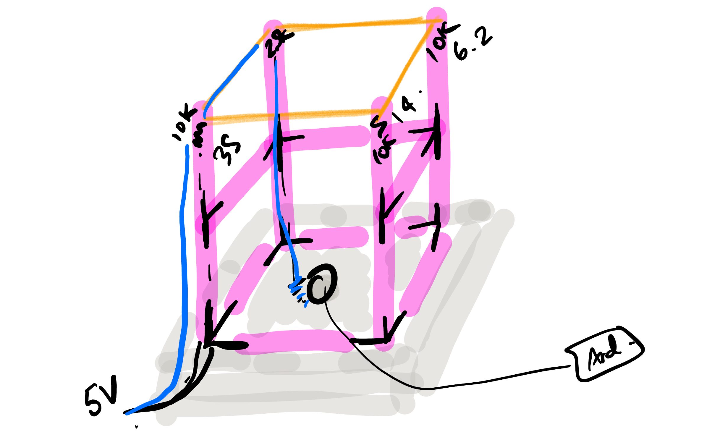
Creating the sword and the cage was a lot of work, but overall, it was relatively straightforward. Unfortunately the cage wasn't nearly as rigid as I was hoping - necessitating that one had to be gentle with the sword when tapping the wires along the top. In the future I would build this out of 2x4s and use copper piping along the top, instead of wires. I really wanted a satisfying "clang" when you used the sword.
So what if it isn't relaxing? It was actually pretty fun.
I was pleased with how the project came together with all the different physical elements. And the people who tried the prototype seemed to find it enjoyable as well. Things to consider in the future is seeing whether using your heel to activate a button would create a better walking experience (rather than usig the ball of the foot/toes as currently designed), and as mentioned, creating a much more rigid cage for the sword striking.
Why did I call it "aka sooo many wires"? Knowing that I'd have to move all the pieces around for the demo, and not knowing exactly where I'd have to place the pieces, that meant I needed 1: flexible wire (28-30 guage), and 2: long lengths of it. To make it somewhat manageable I braided all the pairs of wires, which took a surprisingly long time! For sure next time, I'll need to learn / build a better way to braid wires.
References and Resources
A Blind Legend
A Blind Legend was created in 2015 by developed Dowino, https://en.m.wikipedia.org/wiki/A_Blind_Legend
Sword Hilt
I found a sword hilt from Thingiverse that worked well since it was originally designed to replace the handle on an umbrella, so it had a hole down the center where I could insert the copper pipe. I then used Prusa Slicer to cut another smaller diameter hole all the way through to run the wire which I soldered to the inside of the pipe. Umbrella Sword Hilt on Thingiverse.